Fixed beam deflection calculator for bending moment, deflection and slope calculation of a fixed beam under point load, distributed load and bending moment.
Note : Use dot "." as decimal separator.
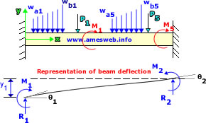
Note * : P is positive in downward direction as shown in the figure and negative
in upward direction. M is positive in clockwise direction as shown in the
figure. wa and wb are positive in downward direction as shown in the figure and negative
in upward direction.
Note ** : For second moment of area calculations of structural beams, visit "
Sectional Properties Calculators".
|
INPUT LOADING TO FIXED BEAM |
|
POINT LOADS |
|
|
|
CONCENTRATED MOMENTS |
|
|
|
DISTRIBUTED LOADS |
|
|
|
RESULTS |
 |
|
Parameter |
Value |
|
Reaction Force 1 [R1] |
---
|
|
|
Reaction Force 2 [R2] |
---
|
|
Transverse Shear Force @ distance x [Vx] |
---
|
|
Maximum Transverse Shear Force [Vmax] |
---
|
|
Reaction Moment 1 [M1] |
---
|
|
|
Reaction Moment 2 [M2] |
---
|
|
Moment @ distance x [Mx] |
---
|
|
Maximum Moment [Mmax] |
---
|
|
Slope 1 [θ1] |
---
|
|
|
Slope 2 [θ2] |
---
|
|
Slope @ distance x [θx] |
---
|
|
Maximum Slope [θmax] |
---
|
|
End Deflection 1 [y1] |
---
|
|
|
End Deflection 2 [y2] |
---
|
|
Deflection @ distance x [yx] |
---
|
|
Maximum Deflection [ymax] |
---
|
|
Bending Stress @ distance x [σx] |
---
|
|
|
Maximum Bending Stress [σmax] |
---
|
Note * : R1 and R2 are vertical end reactions at the left and right, respectively, and are positive upward. Shear forces and deflections are positive in upward direction and negative
in downward direction. M1 and M2 are the reaction end moments at the left and right, respectively. All moments are positive when producing compression on the upper portion of the beam cross
section. All slopes are positive when up and to the right.
Note: Stresses are positive numbers, and these are stress magnitudes in the
beam. It does not distinguish between tension or compression of the structural
beam. This distinction depends on which side of the beam's neutral plane c input
corresponds.

Slope

Deflection

Moment

Shear Force