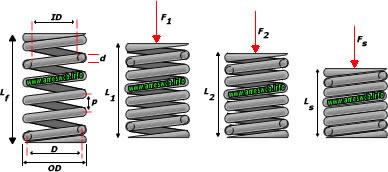
Compression spring calculator to find compression spring
design parameters with the knowledge of design type (one load & free height, one load & spring rate, two loads), compression spring wire diameter, spring diameter, spring free height, loads at specific heights, compression spring end type and material selection. Material selection of compression springs can be done from listed spring steels including music wire, stainless steel wire, chrome vanadium, etc.
Calculation results generated by the compression springs calculator are solid height, torsional
shear stress at solid height, factor of safety against yielding, buckling check,
spring outer diameter expansion, load-deflection curve, stress–deflection curve, spring
index.
This calculator can be used to design statically loaded compression springs. For compression springs
which work under cyclic loading, first use this calculator for the sizing
according to static loading and then visit "Critical Frequency of Helical Springs" and "Stress Analysis of
Coil Compression Springs for Fatigue Loading" calculators to check the compression spring design against cyclic loading.
Compression spring formulas used in the calculator are given in the "Supplements " section of this page.
Note 1 : x Spring material properties are from Ref-2 except "User defined"
selection.
Note 2 : + Equals maximum allowable torsional stress in static
applications. See supplements for reference values.
Note 3 : * Ends supported by flat surfaces must be squared and ground [Ref-2] .
|
RESULTS |
|
DIMENSIONAL PARAMETERS |
|
Parameter |
Value |
|
Number of active coils [Na] |
---
|
--- |
|
Number of total coils [Nt] |
---
|
|
Spring index [C*] |
---
|
|
Spring rate [k] |
---
|
|
|
Wire diameter [d] |
---
|
|
|
Spring outer diameter [OD] |
---
|
|
Spring mean diameter [D] |
---
|
|
Spring inner diameter [ID] |
---
|
|
Outer diameter at solid length [ODat solid***] |
---
|
|
Spring free length (height) [Lf] |
---
|
|
Spring solid height [Ls] |
---
|
|
Maximum deflection (Lf to Ls) [Δx] |
---
|
|
Pitch at free length [p**] |
---
|
|
SPRING MATERIAL & STRESS RELEATED PARAMETERS |
|
Parameter |
Value |
|
Load at solid height [Fs] |
---
|
|
Shear stress at height 1 [τ1]
|
---
|
|
|
Shear stress at height 2 [τ2] |
---
|
|
Shear stress at solid height [τs] |
---
|
|
Ultimate tensile strength of material [Sut] |
---
|
|
Allowable torsional strength [Sall ] |
---
|
Factor of safety against torsional yielding at solid height [foss
(Sall / τs )#] |
---
|
--- |
|
Modulus of rigidity [G] |
---
|
|
|
Elastic modulus [E] |
---
|
|
Material ASTM No. |
---
|
|
SPRING STABILITY (BUCKLING) |
|
Parameter |
Value |
|
Stability condition (includes nb) |
---
|
|
Factor of safety against buckling [fosb+] |
---
|
Note 1 : * The preferred spring index range is 4 to 12 according to [Ref-1] .
Compression springs with high indexes tangle and may require individual
packaging, especially if the ends are not squared. Springs with indexes lower
than 4 are difficult to form [Ref-1] .
Note 2 : ** According to no yielding assumption and Lf length shall be same after loading.
Note 3 : *** Does not include the effect if the spring ends are allowed to unwind.
Note 4 : + Shall be larger than the design factor for buckling (nb
≤ fosb )
Note 5 : # Shall be larger than the design factor at solid height (ns ≤
foss )

Force vs Spring Height

Shear Stress vs Spring Height
Note 1 : The load deflection curve for helical compression springs is
essentially a straight line up to the elastic limit, provided that the amount of
active material is constant. The initial spring rate and the rate as the spring
approaches solid often deviate from the average calculated rate. When it is
necessary to specify a rate, it should be specified between two test heights
which lie within 15 to 85 % of the full deflection range. [From Ref-1]