|
|
OUTPUT PARAMETERS |
|
Parameter |
Value |
|
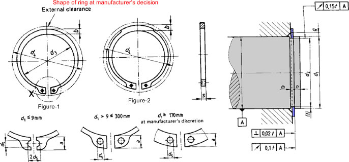
Nominal Shaft Diameter [d1] |
---
|
mm |
|
Clip |
|
Thickness of the Circlip [s] |
---
|
mm |
|
Thickness Upper Deviation [sup_dev] |
---
|
|
Thickness Lower Deviation [Slow_dev] |
---
|
|
Internal Diameter of Circlip (Not under tension) [d3] |
---
|
|
Internal Diameter Upper Deviation [d3_up_dev] |
---
|
|
Internal Diameter Lower Deviation [d3_low_dev] |
---
|
|
Maximum Radial Width of the Lug [amax] |
---
|
|
Beam (Radial Width of Circlip Opposite the Aperture) [b ≈]
Note 1 |
---
|
|
Diameter of Lug Holes [d5_min] |
---
|
|
Weight of 1000 pieces [w ≈] |
---
|
kg |
|
Groove |
|
Groove Diameter [d2] |
---
|
mm |
|
Groove Diameter Upper Deviation [d2_up_dev ] |
---
|
|
Groove Diameter Lower Deviation [d2_low_dev] |
---
|
|
Groove Width [m] |
---
|
|
Groove Depth with Nominal Sizes of d1 and d2 [t] |
---
|
|
Minimum Edge Margin [nmin] |
---
|
|
Supplementary Data Note 2 |
|
Maximum Symmetrical Diameter of Bore during Fitting [d4] |
---
|
mm |
|
Load-bearing Capacity of Groove at a Yield Point of the Grooved Material of 200
MPa [FN] |
---
|
kN |
|
Load-bearing Capacity of Circlip with Sharp-edged Abutment of the Pressing Part
[FR] |
---
|
|
Edge Chamfering Distance of the Abutment Surface to the Circlip [g] |
---
|
mm |
|
Load-bearing Capacity of Circlip for Abutment with Edge Chamfering Distance g [FRg] |
---
|
kN |
|
Detachment Speed of the Circlip [nabl] |
---
|
min-1 |
|
Nominal Size of Pliers according to DIN 5254 |
---
|
--- |